Wake County AUXCOMM
- Home
- About
- AUXCOMM Nets
- News
- Training
- ICS 214 Incident Activity Tracking Log
- ICS review
- Mandatory NIMS Training
- Standardized Phonetic Alphabet
- Standardized Prowords
- ICS-213 Message Handling
- AUXCOMM Power Connector
- Basic Radio Procedures for Activations
- Activation Levels
- State EOC Emergency Operations Plan
- Emergency Communications Declarations
- Go Kit
- Repeaters
- Join
- Archives
Assembling PowerPole Connectors
Assembling Anderson Powerpole connectors is a relatively simple task. There are two main components: the colored plastic housing and the electrical contact.
Colored housings. The plastic housings can be mated to form multiple conductor connector assemblies. In the current case, we will build two-conductor assemblies comprised of one Red and one Black housing and two contacts and one locking pin. See Figure 7 at the end of this document..
Contacts. The contacts may be attached to individual wires by soldering or crimping. The following outline may be helpful in avoiding problems. Note that this is specific to the 30A contacts, but is also applicable to the 15A contacts. The 45A contacts require an additional step to close the sleeve around the wire before soldering or crimping.
Soldering. Attaching wires to Powerpole contacts by soldering is a simple task. There is one preliminary step that will greatly ease the process and that is to “flux” the exposed conductor before beginning the soldering process. This can be easily accomplished by using a “flux pen” (available at Radio Shack) or a non-corrosive liquid flux (preferably water based) prior to inserting the wire into the open contact end.
After stripping the insulation from the wire end, flux the bare end and insert into the open end of the contact. Apply the heated iron tip to the side of the contact barrel and carefully apply small diameter solder to the wire/contact junction at the open end of the contact. Be careful to avoid getting solder on the lip of the contact. Clean the contact to remove any excess flux and insert into the plastic housing.
Crimping. Contacts may be readily crimped onto bare wires by a number of tools. The Anderson full-cycle ratchet tool produces the best joint, but the cost is prohibitive for most Amateur Radio operators and clubs. Other suitable (but not full-cycle ratchet type) tools can produce good joints, given a measure of care. Among these useful tools are those manufactured by Klein, Gardner-Denver and Harbor Freight. After using all of those mentioned, I prefer the Harbor Freight 36411 tool, for a number of reasons, not the least of which is it’s $6 cost. It also has, in addition to a properly sized anvil/die, a forged round forming section that is ideal for fixing mistakes.
The principal contribution to failure when crimping these contacts is allowing the width of the contact to expand during the process. This results in a contact that cannot be properly inserted into the plastic housing. If the crimping tool die is improperly sized (i.e., too big), the contact diameter will be enlarged as it is crimped or will become “flattened” during the process.
The first step in avoiding damage to a contact while crimping is to carefully align the contact into the tool before inserting the wire. I prefer to insert the contact into the anvil/die such that the seam of the contact barrel is adjacent to the die. (Explicitly, this means that the contact is placed into the crimping tool with the seam of the barrel facing the “pointed” side of the crimper). The seam side will be pressed into the wire as the tool is closed. This results in the least enlargement of the diameter of the contact as pressure is applied.
Wire preparation. Prior to soldering or crimping, you must first remove the insulation from the wire. A properly sized wire-stripping tool will make this task easy. For wire sizes 12-14 AWG, strip 1/4 inch of insulation from the conductor. See Figure 2
Figure 2
If you need to attach wires smaller than 14 AWG to a 30A contact, you should strip a longer length, fold the bare conductor in a “Z-fold” fashion and insert the multiple folds of the wire into the contact barrel. This will help to prevent flattening of the contact when it is crimped. See Figure 3
Figure 3
Crimping Tool. The 36411 tool from Harbor Freight (www.harborfreight.com) is shown in Figure 4, below. For those fortunate enough to have a local Harbor Freight store, you can sometimes find this tool on sale for $4.
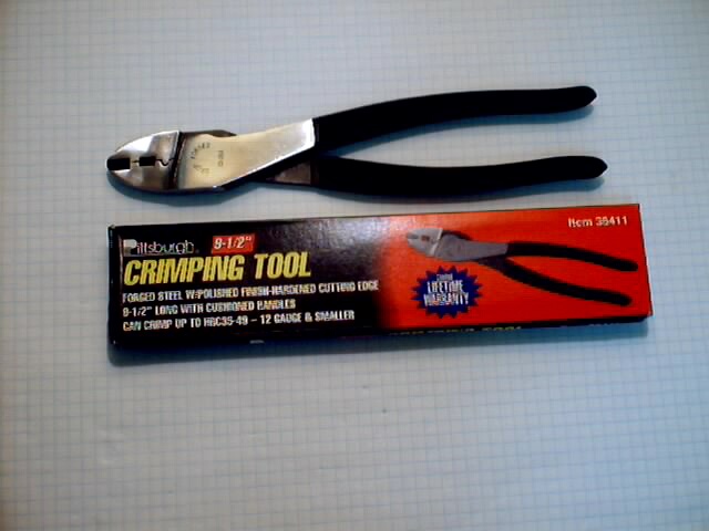
Figure 4
Figure 5 below shows the crimping die and anvil (right side of the jaw) as well as the circular forming section. The die is the part that indents the contact while the anvil side maintains the round shape. The round forming section may be used to reshape a contact that has been distorted during the crimping process.
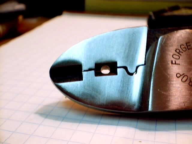
Figure 5
The following photograph shows the anvil and die when the tool jaw is open.
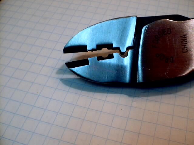
Figure 6
A complete Powerpole connector assembly is shown below in Figure 7.
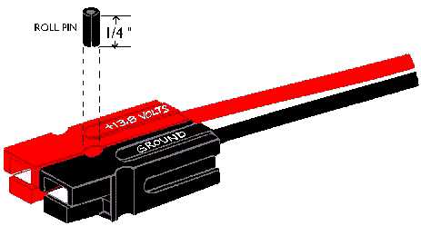
Figure 7